Foreign Insulators
by Marilyn Albers
Reprinted from "Crown Jewels of the Wire", May 1989, page 11
The material presented here this month is basically a repetition of my column
which appeared in the November, 1980, issue of CROWN JEWELS. So it is not new,
but I have a special reason for running it again. Read on.
This fascinating account of The New Trunk Insulator, by R. M. Osborne, was
first published in The Telecommunications Journal of Australia in February,
1939. That's over 50 years ago! It seems that the standard trunk insulator of
Australia at that time was causing problems. By its very design, dirt
accumulated easily on the surface of the bell shaped insulator (U-1502 in Fig.
1.) and in wet weather, this increased the surface leakage between wire and pin,
resulting in low insulation resistance. Sometimes, it was almost impossible to
receive a telephone call for the static. And so, in 1936, came the decision to
re-design the insulator. Four different styles of insulators were tested. You
will recognize U-541 in Fig. 2. and U-1154 in Fig. 3. To our knowledge, no
specimens of the glass insulator shown in Fig. 4. had ever been seen by present
day collectors and it was extremely doubtful that any had survived, though a few
of the older residents living along the Melbourne to Dromana test circuit do
remember seeing them in service there.
Please read the rest of the story now, because I have saved the good news
'til last!
The New Trunk Insulator
R. M. Osborne, M.E.E, A.M.I.E.E.
With the extension of the practice of dialing over trunk lines, troubles
have been experienced on account of the large variation in the insulation
resistance of the aerial circuits used. Some dialing lines, in wet weather, have
an insulation resistance of 10,000 ohms or even less, and become unworkable, and
in 1936 it was decided that the standard trunk insulator should be re-designed
in order to effect, if possible, an improvement in this state of affairs. It was
recognized that, although there are several sources of loss in a telephone
insulator, by far the most important one at voice and telegraph frequencies is
surface leakage between wire and pin, and the object of the designers was, therefore, to reduce this effect.
With a clean insulator the surface leakage,
even in wet weather, is small, but, as dirt accumulates, a semi-conducting path is
formed on the surface if the atmosphere is moist, particularly if the dirt
includes salt or carbon. The resistance of this path depends upon its length and
cross-sectional area in the same way as the resistance of any conductor depends
upon these variables, and it is therefore desirable to make the length of the
path as great as possible whilst, at the same time, keeping its cross-section
area as small as possible, i.e., by keeping the circumference of the insulator
as small as possible.
This result is partially achieved in many insulators by using two skirts.
The trunk insulator which has been standard in Australia for many years is one
design which incorporates this feature, and so is the B.P.O. trunk insulator.
These two designs are shown in Figs. 1 and 2. Examination of them shows that the
B.P.O. insulator provides a longer leakage path between wire and pin (32 cms. as
compared with 23 cms.), and at the same time the average diameter of the leakage
surface is considerably less (4.60 cms. as compared with 7.54 cms.). Thus, if
each of the insulators has an equal thickness of similar deposit upon it, the
surface resistance of the B.P.O. insulator will be nearly 2.3 times as great as
that of the Australian trunk insulator. In addition, exposure tests conducted at
the Research Laboratories indicated that the external surface of the Australian
insulator which curves outwards is more likely to accumulate dirt than the
straight vertical sides of the B.P.O. design.
It was therefore decided to use
the B.P.O. insulator as the basis for design, but to attempt to make it suitable for use
with wooden spindles which, in Australia, are more economical than steel
spindles. The use of wooden spindles would necessitate increasing the diameter, for it would not be practicable to
obtain a sufficiently strong wooden spindle to fit the thread of the B.P.O.
design.
This increase of diameter would tend to reduce the surface leakage resistance
and also would increase the weight of the insulator; it would therefore be
undesirable. Instead of abandoning the wooden spindle the designers decided to
depart from the B.P.O. practice and eliminate the second skirt. They argued
that, although by doing so they would reduce the length of the leakage path,
they would also reduce the average diameter of the insulator, and thus the two
effects would partly cancel out. Furthermore, they believed that the outer surface, which is continually washed by rain, is the most important part, and that
the elimination of the inner skirt would not be as serious as might be imagined.
To obtain the maximum benefit, however, a wooden spindle of minimum practicable
diameter was designed for use with the new insulator, the final design of which
is shown in Fig. 3. It is hoped that, when tests have been completed, this
insulator will become the Australian Standard Trunk Insulator.
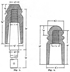
The length of the
surface leakage path of this insulator is slightly less than that of the old
trunk insulator (18 cms. as compared with 23 cms.) but its average diameter is considerably less (5.08 cms. as compared
with 7.54 cms.) and therefore its theoretical surface leakage resistance is greater than that of
the old design. Furthermore, as stated above, a large proportion (57 per cent.)
of its leakage path is exposed to the cleansing action of rain. With the old
trunk insulator, this proportion is 87 per cent. and with the B.P.O. insulator
it is 32 per cent. The designers hope that this feature of the new insulator
will largely compensate for the higher theoretical leakage resistance of the
B.P.O. insulator.
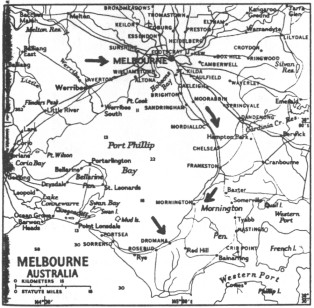
After the design had been completed, it was decided to conduct
field tests by installing the insulators on the Melbourne-Geelong trunk route
but, before this was done, the decision to scrap this route made other plans
necessary, and it was decided to equip certain lines between Melbourne and
Dromana which were known to have very low insulation resistance during periods
of high humidity. It was. intended to equip one circuit with the new insulators
made of porcelain, and one circuit with B.P.O. porcelain insulators, and to
compare the results obtained with the standard Australian porcelain insulators
erected on the same poles. It was then thought advisable to make some of the new
insulators in glass in order that the value of this material for the purpose
could be examined. The Australian Glass Go. agreed to co-operate but pointed out
that the new design, although suitable for porcelain, was not ideal for glass
because of the cooling stresses likely to be set up in the body of the
insulator. They submitted a design which gave the same leakage path but which,
they considered, would be better for glass, and the Department purchased
sufficient of these insulators to equip a circuit between Melbourne and Dromana.
Fig. 4 shows a glass insulator of the design tested.
The installation of the insulators on the Melbourne-Dromana circuits was completed in March, 1938, and each of the
circuits was connected to the Research Laboratories by an underground cable
pair between the Glenhuntly cable head at the Melbourne end of the circuits,
and the Laboratories, and a recording galvanometer was arranged to record the
insulation resistance of each of the circuits. The method of connection did not
affect the usefulness of the circuits for their normal traffic, and they were not, therefore, withdrawn
from service. Before tests commenced, the insulators on these lines were cleaned
by spraying them from the ground.
In July, 1938, the first analysis of the
results was made. As was known, the insulation of the various lines varied
considerably with the humidity, and in order to compare the results, it was
therefore necessary to compare the readings at equal humidities, and for the
purpose of these tests, the readings at high humidities are, of course, the most
important because it is under these conditions that lowest insulations occur.
Some variations occurred in the day by day readings, but the lowest insulation
resistances recorded at any time were as under: --
B.P.O. Standard
|
38,000 ohms.
|
Australian Single Skirt--
|
|
Porcelain
|
34,000 ohms.
|
Glass
|
14,000 ohms.
|
Australian
Double Skirt (old design)
|
5,000 ohms.
|
These readings are the overall readings
between wires of the lines which are approximately 46 miles long; the lowest
readings at other humidities were in about the same order. For example, at 80
per cent. they were:--
B.P.O. Standard
|
450,000
|
Australian Single Skirt--
|
|
Porcelain
|
450,000
|
Glass
|
160,000
|
Australian Double Skirt (old de sign)
|
50,000
|
These results
are very satisfactory and, so far, confirm the designers' belief in the single
skirt design. It would be unwise to be unduly optimistic until further results
have been obtained and the effect of weathering has been ascertained, but on the
results so far, the Department has felt justified in purchasing large supplies
of trunk insulators to the new design. This will, of course, introduce
complications such as are always met when an old standard is replaced by a
new, but it is felt that the advantages to be obtained are very real and far
outweigh the objections.
The reason for the low value of the glass insulator is not very clear at
present, but it is possibly due to the presence of cracked insulators on the
line. During installation, some of these insulators cracked and a number actually
broke. Whatever the reason, however, the results so far reflect some
inferiority of the glass insulators installed for test, which may or may not
become more pronounced as the tests proceed.
It is possible that an extra groove may be added to the design of Fig. 3, but
unless future tests cause opinions to be modified considerably, it is probable
that no drastic alterations to it will be made and that it will become the new
Departmental Standard, and will be known as Insulator, Trunk, L.S. (Long Skirt)
to distinguish it from the present Trunk Insulator. The new wooden spindle for
use with it has already been designed, and designs for the necessary steel
spindles are in course of preparation.
As a matter of interest it is recorded
that a number of these new insulators were installed on junction lines from McLaren Vale
Exchange is South Australia. These lines had previously been very unsatisfactory in damp and foggy weather, but since the installation of the new
insulator have been satisfactory. It is hoped that the general introduction of
the new insulator will have similar satisfactory results in many parts of the Commonwealth.
So what's the good news? Two of these early double grooved glass insulators
have surfaced! They came out of a "closet collection" in New York
early this year -- a case where, some time ago, a friend of this particular
collector had brought him some insulators from Australia. These rare jewels were
among them and have been safely tucked away all these years. Mike Guthrie gets a
star in his crown for bringing them out into the light of day. It's been a long
time since I've been quite this excited over a new find. After careful
inspection by "Woody", it has been given CD number 432. Although the
insulator was definitely made in 1938 for testing purposes by the Australian
Glass Manufacturing Company of Sydney, it is completely unembossed The color of
glass is a pale greyish sage green.
This insulator was (and is) quite fragile and, as the article stated, many
cracked and were broken while in service on the line. This explains their high
mortality rate. It is easy to see why this particular design eventually evolved
into the heavier, chunkier style so widely used today in Australia -- CD 420 (old
130.7) The first CD 430's were made by CROWN CRYSTAL GLASS, also of Sydney, and
were marked C.C.G. See both examples in the photo below.
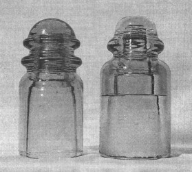
New CD 432 on the left and the familiar CD 430 on right
To date, we have identified 11 styles of insulators that were manufactured in
Australia from 1931 to 1962. These are shown in the drawings that follow on the
next page. Notice that the slight variations in CD's 490 and 590 do not change
the number.
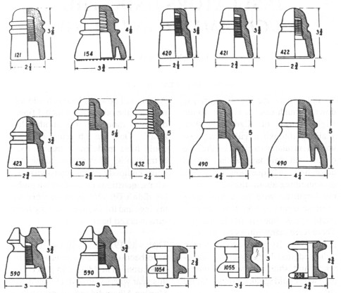
1931 - 1948 AUSTRALIAN GLASS MANUFACTURING COMPANY, Sydney
CD's 121, 154, 420,
421, 422, 490. Units marked with trade name "AGEE"
1948 - 1950 CROWN CRYSTAL GLASS, Sydney
CD's 422,423, 430. Units marked
C.C.G.
1950 -1962 AUSTRALIAN GLASS MANUFACTURING COMPANY, Hobart, Tasmania
CD's 423,
430, 590, 1954, 1055, 1058. Units marked A.G.M.
|

)
)
)
)
)
)